GATEの使い方 4 ~digitizerの設定~

How to use GATE 4

今回は情報の読み出し(Digitizer)と呼ばれる機能についてです。
This article explain about “readout (Digitizer)” function.
GATEではどんな粒子が、どんなVolumeの中で、どのような相互作用をして、どれくらいエネルギーを落としたかなどの情報(Hit)を取得可能です。
We can obtain “Hit” information (particle, volume, interaction, energy deposit etc…) from GATE simulation.
しかし、現実世界においてはそのような情報は取得できません。この情報を実測できる形(Single)に処理する機能がDigitizerであり、エネルギー分解能等はここで組み込みます。
However, it is impossible to get these information in real experiments. Digitizer function change these Hits information to Singles which can be obtained in real. For instance, energy resolution is considered in this process.
これを読めば情報の読み出し(Digitizer)に関して(おおよそ)の理解ができます!(難しいので間違っている場所もあるかと思います)
You can understand roughly about “readout (Digitizer)” if you read this article, however this content is difficult so there may be mistakes.

GATEの使い方 4
How to use the GATE
Digitizerとは
What is Digitizer ?
GATEで情報を取得できるのはSensitive detector(SD)に登録されたクリスタルおよびファントムの中だけです。粒子はStepと呼ばれる小さな単位でシミュレーション体系を進みます。
In GATE simulation, you can get all information during particle is in the volume which is registered to crystal sensitive detector (SD) or phantomSD.
粒子は多くのstepのあと、しきい値以下のエネルギーになるかシミュレーション体系から飛び出すかによって消滅します(追跡しなくなる)。
Particles go through inside of the volume in “Step” units. Particle disappear when the energy of the particle is less than threshold or go outside from the world.
このstepから得られる情報をHitといいます。しかし、実測で得られる情報はクリスタルにどのくらいのエネルギー付与があったかだけであり、それも装置のエネルギー分解能によってボケた後の値です。
The information obtained from “step” is called “Hit”. However, the only information that can be obtained by actual measurement is how much energy deposit to the crystal. Moreover, this energy deposit was blurred in accordance with the energy resolution of the system.
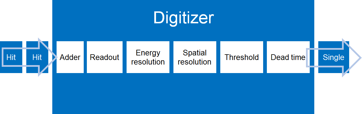
一つの粒子がSensitive detectorの中で起こす相互作用は0回~複数回あり、その分だけHitの情報が得られます。このHitの情報はDigitizerで処理されSingleとなります。上の図は大まかな流れを示してます。
One particle interact with sensitive detector in several times. One interaction generate one Hit information. This “Hit” information is processed by digitizer module and change to “Single”. Above figure shows the flow of the digitizer.
・Adder:加算
・Readout:読み出し
・Energy resolution:エネルギーのボケ
・Spatial resolution:検出位置のボケ(ECAT only)
・Threshold:検出するエネルギーの下限/上限
・Dead time:不感時間
などが代表例です。
The above examples are some of the typical objections.
PETの場合は、SingleとSingleの関係からCoincidenceとなるかを決める処理も組み込まれます。
In the case of PET simulation, processing to decide whether to become Coincidence from the relationship between Single and Single is also incorporated.
このようにDigitizer処理は一連の流れで処理されます。これらのコマンドは順番も重要です。
Digitizer processes are executed as a series of flow. The order of digitizer process is important.
・Adder->Readout
・Readout->Threshold
・Blurring->Threshold
間違わないようサンプルコードに従いましょう。
You should obey the sample code in order not to make a mistake.
Digitizerの処理は前回のコードで言うと、ここの部分です
Digitizer process is shown in previous code.
#=========================================
#   D I G I T I Z E R: DETECTOR ELECTRONIC RESPONSE
#=========================================

/gate/digitizer/Singles/insert       adder
/gate/digitizer/Singles/insert        readout
/gate/digitizer/Singles/readout/setDepth    1

/gate/digitizer/Singles/insert   blurring
/gate/digitizer/Singles/blurring/setResolution   0.094
/gate/digitizer/Singles/blurring/setEnergyOfReference    511. keV

/gate/digitizer/Singles/insert     thresholder
/gate/digitizer/Singles/thresholder/setThreshold    425. keV
/gate/digitizer/Singles/insert    upholder
/gate/digitizer/Singles/upholder/setUphold   650. keV

#=========================================
#	C O I N C I D E N C E    S O R T E R
#=========================================

/gate/digitizer/Coincidences/setWindow      4.9 ns

/gate/digitizer/name     delay
/gate/digitizer/insert     coincidenceSorter
/gate/digitizer/delay/setWindow    4.9. ns
/gate/digitizer/delay/setOffset 500. ns上に描いた処理以外にも電気回路のノイズやクリスタル毎のエネルギーおよび検出位置のボケ、量子効率、クロストーク、情報の転送速度の影響、パイルアップなど様々な因子を考慮できます。しかし、自分の施設で使用しているPET装置のこれらの情報を入手するのは困難です。
There are many factor such as electronics noise, blur of the detection position in each crystal, quantum Efficiency, cross-talk, transfer speed, pile-up can be considered in addition the process shown above. However, it is hard to get these information of the PET using at our facility.
なので、実機と同じ処理を模擬するのではなく、許容できる範囲の画像を得ることを目的にするのがいいと思います。装置の設計をするような工学系の方々はこれらの詳細な条件設定が求められるのだと思います。
It is reasonable not to simulate real processing but to get acceptable PET images in the simulation. Engineer who design a PET device may be wanted to simulate in more detail.
私は医療従事者なので、それでいいです
It is OK, because I am medical staff.
もし詳細なdigitizerの処理が必要な場合は、マニュアルの該当する部分のコードをコピペして、値を書き換えてくださいね。
If you need to use digitizer process exactly, please refer the official manual. You can copy and use by editing it.
加算器
Adder
同じVolume内で起こったHit情報を加算するprocessになります。Digitizerの処理の中で最初に書く必要があります。
Adder process add the “Hit” information generated from same volume (or module). You need to write about “Adder” at the beginning of digitizer section.
/gate/digitizer/Singles/insert adderこの一行を書くだけです。
All you have to do is write above sentence.
読み出し
Read out
読み出し方法には2つあります。
There are two ways.
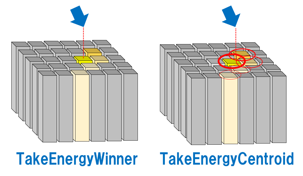
1.Winner-take-all方式(勝者総取り)(TakeEnergyWinner)
最もエネルギー付与が大きかったVolumeの中心座標を採用
Get a central coordinate of the volume which took the highest energy deposit.

2.Anger方式(TakeEnergyCentroid)
エネルギー付与の割合に応じて重心計算する
Calculation of barycentric position from the ratio of energy deposit.

# Readout
/gate/digitizer/Singles/insert readout

/gate/digitizer/Singles/readout/setPolicy TakeEnergyWinner
#   or
/gate/digitizer/Singles/readout/setPolicy  TakeEnergyCentroid

/gate/digitizer/Singles/readout/setDepth number (=1,2,3....)中段のsetPolicyをどちらかだけ指定する必要があります。
また、TakeEnergyCentroidを選択した場合、最後のsetDepthは無視されます。
ちなみのsetPolicyを指定しなかった場合は、TakeEnergyWinnerがデフォルトとして選択されることになります。
You have to choose one of setPolicy. The value of the setDepth is ignored when you choose “TakeEnergyCentroid”.
If you do not specify setPolicy, it turn on TakeEnergyWinner mode.
ではここで、簡単な実験を行いましょう。
Let’s conduct a simple experiment.
前回構築したPET装置から円柱ファントムを除外します。
その代わりに中心座標(0, 0, 0)に直径1mm、長さ1mmの18F点線源を配置します。
I remove cylindrical phantom from previous code.
Point source (18F, diameter:1mm, length:1mm) is placed at the center of the world.
各Volumeは以下のようにシステムにattachされています。
Each volume is attached to PET system as shown bellow.
/gate/systems/cylindricalPET/rsector/attach              detector_blocks
/gate/systems/cylindricalPET/module/attach               block
/gate/systems/cylindricalPET/crystal/attach crystal| Attach keyword argument | depth for readout | |
| CylindricalPET | rsector | 1 |
| module | 2 | |
| submodule | 3 | |
| crystal | 4 | |
| layer | 5 |
今回はsubmoduleとlayerがないPET装置なので情報の読み出しは
depth=1, 2, 4のどれかを指定することになります。では同じ条件でシミュレーションしてdepthだけ変えると結果はどうなるのでしょうか?
To read out the information, depth must be 1, 2, or 4 because I did not use “submodule (depth=3)” and “layer (depth=5)”.
What will happen when we change the depth only ?
100kBqの18F点線源を100s間撮像しました。
結果の解釈が難しくなるため、エネルギー分解能は考慮しませんでした。
I acquired point source (18F, 100kBq) for 100s.
I did not consider energy resolution for brevity.
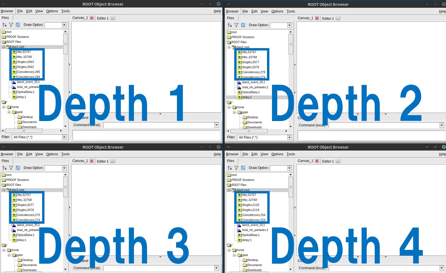
Depth=1
Hits:32767000
Singles:2663000
Coincidences:285000
Depth=2
Hits:32767000
Singles:2677000
Coincidences:275000
Depth=3
Hits:32767000
Singles:2677000
Coincidences:275000
Depth=4
Hits:32767000
Singles:2120000
Coincidences:154000
この結果から言えること
From this result
・Hitsは同じ(Digitizer処理前)
・Depth1>Depth2=Depth3>Depth4の順でSinglesおよびCoincidencesが多い
・submoduleのないPET装置でDepth3を使用した場合にはDepth2の結果と同じになる
・Every Hits (Before digitizer processing) are the same counts.
・The amount of “Singles” and “Coincidences” were increased in order Depth1>Depth2=Depth3>Depth4.
・If Depth3 is specified on a PET device without submodule, the result will be the same as Depth2.
今回はsubmoduleがないためDepth3を指定するのは不適切ですが、それより1つ上のDepth2と結果が同じになるんですね。
では、なぜDepth4のカウントは少なくなるのでしょうか?
Previous code did not include submodule, so to specify 3 to the “Depth” is not proper. However, the same results compared to “Depth:2” were obtained. Why the number of counts decrease in the situation of “Depth:4” ?
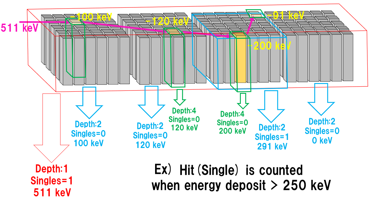
信号が加算(Add)されるのは「depth for readout」と「depth」が等しいVolumeです。ややこしいですね、つまりdepth=2としたなら、module(depth for readout=2)の中の情報がAddされて読み出されるという意味です。
When “depth for readout” and “depth” is equal, “Hit” are added. In other word, if you specify 2 to the depth, “Hits” are integrated to “single” at the module (depth for readout=2) volume.
この図から分かるようにDepthが浅いほど感度は高くなります。Depth4で検出されるのは1つのクリスタルで(例えば)250 keV以上のエネルギー付与があった場合なので起こる確率は低くなります。
ただし、閾値が低い場合(50 keV)などはDepth1ではSingleが1つしか出力されないのに対し、Depth4では多くのSingleが出力されるため、いつも上のような結果になるとは限りません。
When we use shallow “Depth”, the sensitivity is increased as shown above figure. It rarely happens energy deposit more than 250 keV (for instance) in single crystal, so the number of counts decrease when we specify 4 to the “Depth”.
However, this is not always the case. When threshold energy is low (for instance, 50 keV), many “Signals” are generated in depth4 even though one “Single” is generated in depth1.
今回の場合(TakeEnergyWinner)はDepth1でもDepth2でも検出する座標はエネルギー付与が200 keVあったクリスタルの座標になる(はずです)。
(追記:そんなことないかも)
When we use TakeEnergyWinner rule, obtained coordinate (the crystal absorbed more than 200 keV) is same even if we specify 1 or 2 to “Depth”.
Maybe not. ????
2つのサンプルコード(CylindricalPET、ECAT)は共にdepth=1としています。Depth1とDepth2の差は小さかったです。
Both sample code (CylindricalPET and ECAT) use “depth:1”. The difference in both case (depth:1, depth:2) was small in this experiment.
エネルギーのボケ
Energy blurring
PET装置のエネルギー分解能はクリスタルや光電素子(SiPMやPMT)の組み合わせに依存します。現在の装置では10~20%程度だと思います。511 keVのガンマ線が光電吸収されたとしても、出力は400~650keV程度の範囲でバラつきがあります。シミュレーションではこれを意図的に考慮する必要があります。
Energy resolution of PET device is depended on the combination of crystal and photo-electronic device. Most PET device has 10~20 % energy resolution these days. Output is blurred to 400~650 keV even if 511 keV gamma rays are detected. We need to simulate this phenomenon intentionally.
考慮する方法は2つ(逆二乗則と線形法則)あるようです。マニュアルの例題を以下に示します。
According to official manual, there are two ways (inverse square law and linear law) to consider energy blurring as shown below.
/gate/digitizer/Singles/blurring
/gate/digitizer/Singles/blurring/setLaw inverseSquare
/gate/digitizer/Singles/blurring/inverseSquare/setResolution 0.15
/gate/digitizer/Singles/blurring/inverseSquare/setEnergyOfReference 511. keV
もしくは Or
/gate/digitizer/Singles/blurring
/gate/digitizer/Singles/blurring/setLaw linear
/gate/digitizer/Singles/blurring/linear/setResolution 0.15
/gate/digitizer/Singles/blurring/linear/setEnergyOfReference 511. keV
/gate/digitizer/Singles/blurring/linear/setSlope -0.055 1/MeV
どちらも15%@511keVの応答を示します。
Both example indicate the action of 15%@511keV.
ここでも同じ条件でシミュレーションをし、エネルギー分解能のみを変えた場合の結果を示します。
計算条件は先ほどの計算から以下の点で異なります。
・Depth=2で固定
・放射能は1000Bqで計算時間は10s
・エネルギー分解能を10%,20%,30%,40%@511keV
としました。
I conducted a simple experiment. I changed energy resolution only.
Condition of the calculation is shown bellow.
・Depth is 2
・Source is 1000Bq and acquisition time is 10s.
・Energy resolution (10%, 20%, 30%, 40%@511keV)
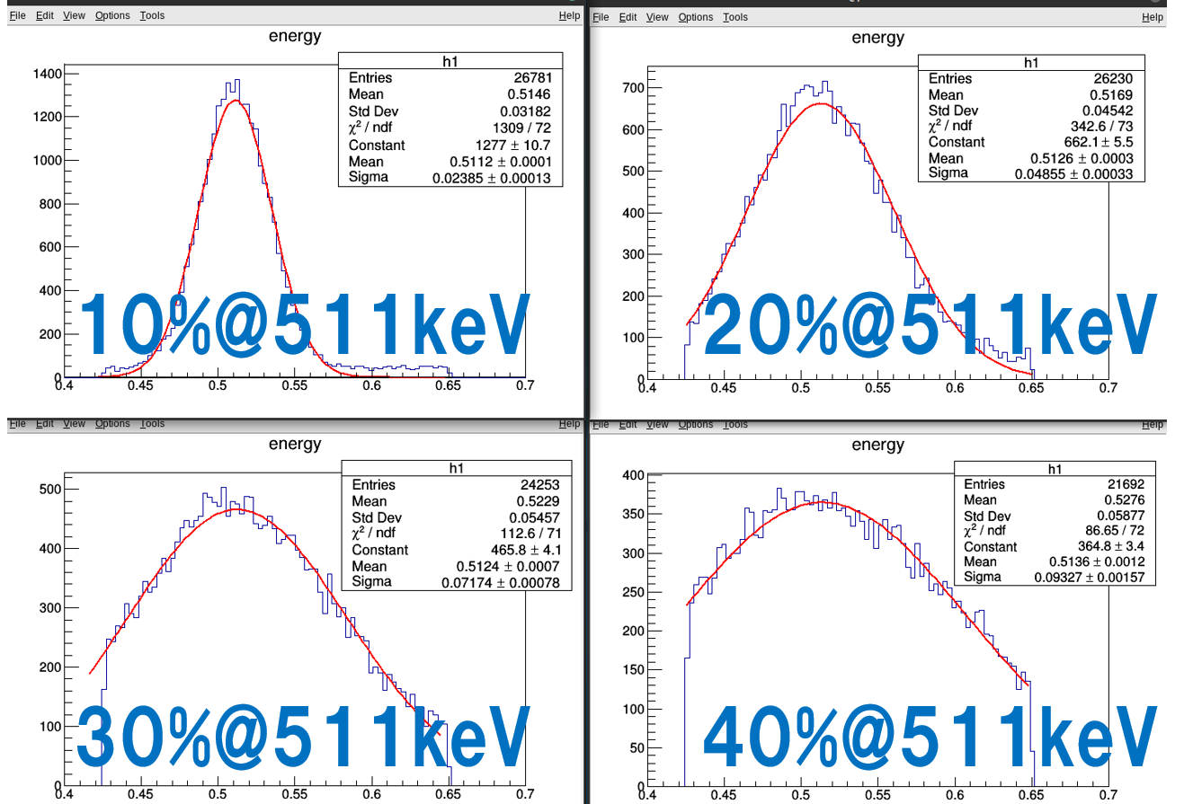
FWHM=2.35*sigmaなので …
10%@511keV
(2.35*0.0239)=0.0562, 0.0562/0.511=0.11
20%@511keV
(2.35*0.0486)=0.114, 0.114/0.511=0.22
30%@511keV
(2.35*0.0717)=0.168, 0.168/0.511=0.33
40%@511keV
(2.35*0.0933)=0.219, 0.219/0.511=0.43
閾値の影響で分解能が悪いほど誤差が大きくなっていますが、だいたい設定どおりの結果が得られています。
Error became large because of effect of threshold. However we got the results as expected.
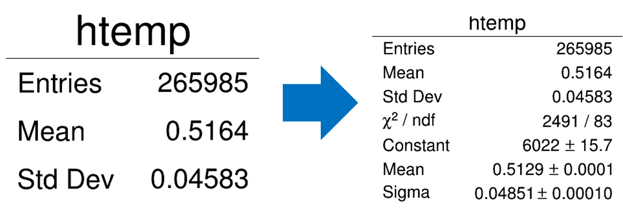
ちなみに上の図はROOTで作成しており、ROOTファイルを開いたあと、
By the way, we made above figure by ROOT. After open the ROOT file …
Singles->Draw("energy>>h1(100,0.4,0.7)")と打ってください。0.4~0.7MeVの範囲を100分割で表示するという意味です。
Please put above command. This command indicate to show the figure at the range of 0.4~0.7 MeV (divided into 100).
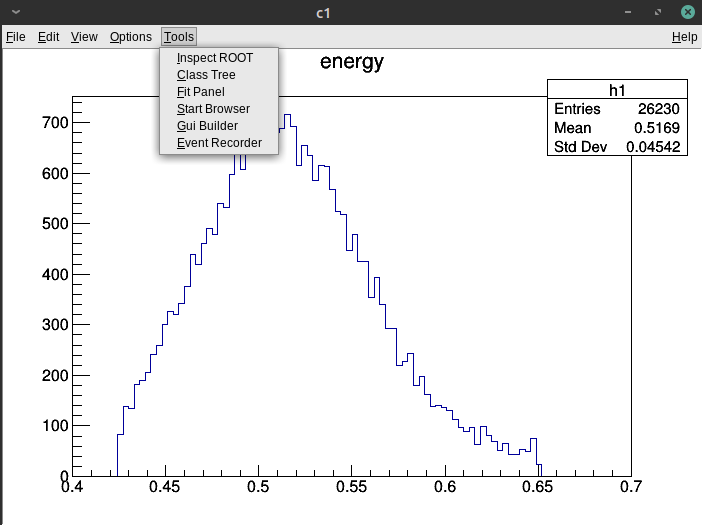
上の図が開きます。次に上のバーから「Tools->Fit Panel」
Figure appear and you select “Tools->Fit Panel” from upside bar.
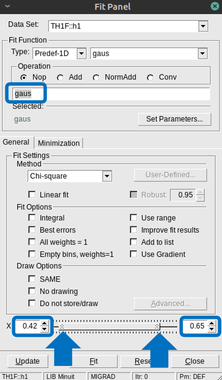
範囲を指定してガウス関数でFittingします。
Fitting by specifying the range and using “gaus” function.
最後に下の図のように 「Options->Fit Parameters」
Finally, as shown bellow figure, select “Options->Fit Parameters”.
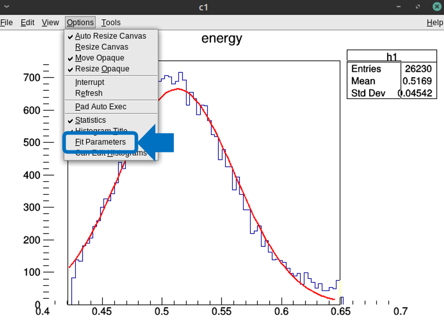
詳細に表示されます
Show in detail.
エネルギーウィンドウ
Energy window (Threshold, Uphold)
エネルギーのボケがないのが理想ですが、実際にはそうはいきません。直接線を極力取りこぼし無く、かつ散乱線(+パイルアップ)が入り込むのを防ぐ必要があり、適切なエネルギーウィンドウの設定が必要になります。これは主にクリスタル(BGOかLSO)の種類で決まってきます。
It it idealed to get the energy without blurring, but it is impossible.
Optimization of energy window is necessary to get the non-scatter ray without missing and prevent mixing scatter ray (or pile-up). Main factor decide energy windows is the kind of crystal (BGO, LSO).
/gate/digitizer/Singles/insert thresholder
/gate/digitizer/Singles/thresholder/setThreshold 420. keV
/gate/digitizer/Singles/insert upholder
/gate/digitizer/Singles/upholder/setUphold 650. keV
全同時計数と遅延同時計数の時間ウィンドウ
Time windows of prompt and delay coincidences
例えば12nsの同時計数ウィンドウを設定するには以下のように指定します。
When you set 12 ns to coincidence time window, you need to write command in macro file as bellow.
#Prompt coincidences
/gate/digitizer/Coincidences/setWindow 12 ns
/gate/digitizer/Coincidences/setOffset 0. ns
/gate/digitizer/Coincidences/describe

#Delay coincidences
/gate/digitizer/name delay
/gate/digitizer/insert coincidenceSorter
/gate/digitizer/delay/setWindow 12. ns
/gate/digitizer/delay/setOffset 500. ns
/gate/digitizer/delay/describe

#Final coincidences
/gate/digitizer/name finalCoinc
/gate/digitizer/insert coincidenceChain
/gate/digitizer/finalCoinc/addInputName delay
/gate/digitizer/finalCoinc/addInputName Coincidences
/gate/digitizer/finalCoinc/usePriority true
/gate/digitizer/finalCoinc/describe

#output
/gate/output/root/setRootdelayFlag    1
遅延同時計数のウィンドウも同じ長さのウィンドウ(12ns)とします。
ROOTファイルに出力するためにはFlagを1とします。
You have to set the same length (12 ns) to the “Delay”.
You flag “setROOTdelayFlag” if you want to get the delay coincidence in ROOT file.
Depth:2
18F point source:1MBq
Acquisition time:1s
とすると以下の結果が得られました
I got the result as bellow.
Coinciences: 28791 counts
delay: 621 counts
finalCoinc: 28791 counts
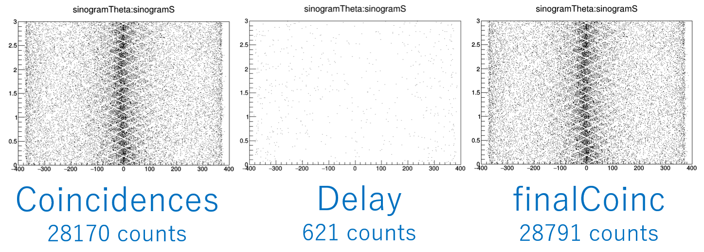
From this results.
finalCoinc = Coincidences + Delay
Coincidences = True+Scatter coincidences
Delay = Random coincidences
まだまだ理解が足りませんが、徐々に追記していこうかと思います。
I still don’t have enough understanding, but I’ll add it gradually.