GATEの使い方 11 ~SPECT~

How to use GATE 11

今回はまたサンプルコードの紹介をします。SPECT検査を模擬する最もシンプルなサンプルです。
This time, I will introduce the sample code. This is the simplest sample that simulates the SPECT examination.
SPECT検査を扱ったサンプルコードはいくつかあります(高速化したものなど)。ですが、やっぱり最初はシンプルなものからやっていきます。
There are several sample codes for SPECT examination (e.g., variance reduction), but we’ll start with a simple sample.
線源および検出器ヘッドの両方が動く例題になっています。以前の記事(Geometry1 and Source1)の内容の復習になると思います。
This sample code makes move both the source and the detector head. I think this article will be a review of the previous articles (Geometry1 and Source1).
これを読めばサンプルコード「SPECT」が理解できます!
If you read this, you can understand the sample code “SPECT”.
GATEの使い方 11
How to use the GATE
サンプルコードの場所 Placement of sample code
本記事で扱うサンプルコードは
The sample code which is explained in this article;
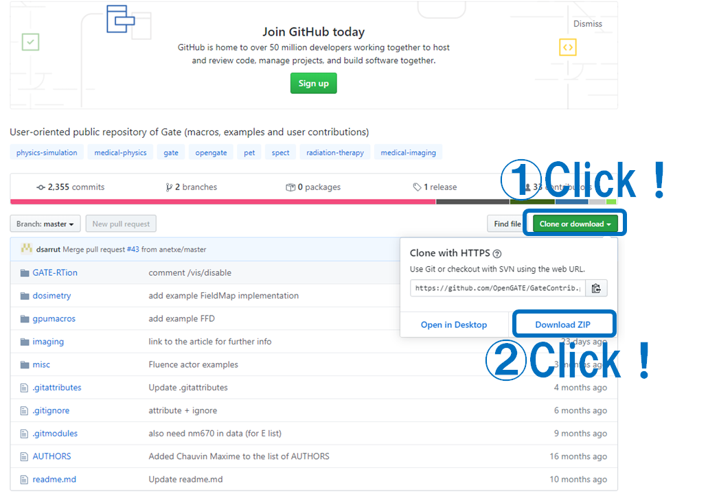
GateContrib/imaging/SPECTにあります。GateContribディレクトリが無い場合はこちらからダウンロードして解凍してください。
is here! If you don’t have GateContrib directory, you should get it from here!
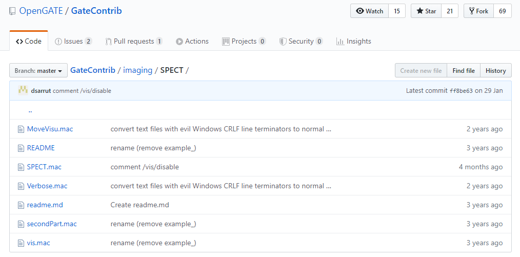
SPECTディレクトリの中身は以下のようになっています。
Contents of the SPECT directory is …
readme.mdにも書かれていますが、このサンプルコードは
As you can see on readme.md, this sample code simulate:
・平行多孔コリメータを装着したSPECT装置(NaI)を4台配置する
・Four SPECT head (NaI) equipped with parallel-hole collimators.
・水の円柱ファントムから140keVのガンマ線を放出する
・Emit 140 keV gamma rays from a water column phantom
という状況を模擬します。
サンプルコードの構成 Structure of sample code
サンプルコードは主に2つ(SPECT.mac & secondPart.mac)に分かれます。
The sample consists of two main codes: SPECT.mac & secondPart.mac.
SPECT.macがまず初めに読まれ、SPECT.macの最後の行で
SPECT.mac is executed first, and secondPart.mac is loaded at the last line of SPECT.mac.
/control/execute secondPart.macとして、secondPart.macを読み込んでいます。
なので、実行する場合には
So, when you run the code
Gate SPECT.macとすれば大丈夫です。
all you have to do is execute the above command.
SPECT.mac
ではSPECT.macの中から順番に見ていきましょう。
Let’s read the contents of SPECT.mac.
Visualization
# V I S U A L I S A T I O N
#####
#/vis/disable
/control/execute vis.mac

# M A N D A T O R Y
#####
/gate/geometry/setMaterialDatabase ../../misc/GateMaterials.db
まず初めに可視化に関する設定をします。本格的に計算をする場合には計算時間を短縮するため可視化はOFFとします。(/vis/disableを有効にする)
The first thing you need to do is set the visualization settings.When calculating in earnest, the visualization is turned off to shorten the calculation time. (/vis/disable is enabled)
しかし、今回はコードを実行しながら視覚的に確認したいと思いますので/control/execute vis.macを有効にします。
However, this time I want to check visually while executing the code, so enable /control/execute vis.mac.
ここで、vis.macが読み込まれました。vis.macが同じディレクトリにありますので、中身を見てみましょう。
By now, vis.mac has been loaded. vis.mac is in the same directory, so let’s take a look at its contents.
#	V I S U A L I S A T I O N
/vis/open OGLSX              #可視化に使う方法
/vis/viewer/set/viewpointThetaPhi 60 60          #描出する視点(角度)
/vis/viewer/zoom 1.5           #拡大率
/vis/drawVolume           #描画
/vis/viewer/flush           #更新
/tracking/verbose 0        #ログの細かさ
/tracking/storeTrajectory 1     #粒子の軌跡を保存する
/vis/scene/add/trajectories      #軌跡を積算していく(重ねていく)
/vis/scene/endOfEventAction accumulate #100イベント(default)ごとに更新/vis/~のコマンドの意味はこのページを見るといいです。もしくはhelpコマンドで調べることができます。
See this page for the meaning of the /vis/~ command. Or you can check with the help command.
Geometry
ではSPECT.macに戻ります。
Let’s go back. (returns to SPEC.mac.)
# G E O M E T R Y
#####

# World
# Define the world dimensions
##
/gate/world/geometry/setXLength 100 cm
/gate/world/geometry/setYLength 100 cm
/gate/world/geometry/setZLength 100 cm
worldの大きさを設定しています。一辺が100 cmの立方体としています。
The size of world is set. The world is a cube with 100 cm on each side.
以降はSPECTの検出器の模擬です。
The following is a simulation of the SPECT detector.
# Scanner Head
# Create a new box representing the main head-volume
# SPECThead is the name of the predefined SPECT system
# Create the SPECT system, which will yield an Interfile output of projection data
##
/gate/world/daughters/name SPECThead
/gate/world/daughters/insert box
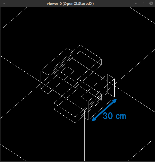
/gate/SPECThead/geometry/setXLength 7. cm
/gate/SPECThead/geometry/setYLength 21. cm
/gate/SPECThead/geometry/setZLength 30. cm
/gate/SPECThead/placement/setTranslation 20.0 0. 0. cm
/gate/SPECThead/setMaterial Air
/gate/SPECThead/repeaters/insert ring
/gate/SPECThead/ring/setRepeatNumber 4
/gate/SPECThead/moves/insert orbiting
/gate/SPECThead/orbiting/setSpeed 0.15 deg/s
/gate/SPECThead/orbiting/setPoint1 0 0 0 cm
/gate/SPECThead/orbiting/setPoint2 0 0 1 cm
/gate/SPECThead/vis/forceWireframe名前はSPECTheadとしています。これは変更しないほうがいいです(多分)。このページにも書かれているように、システムで定義されています。
The name is SPECThead. This should not be changed (maybe). As defined on this page, it is system defined.
大きさはx,y,z軸にそれぞれ7cm, 21cm, 30cmです。
最初の1つが中心からx軸に20cmずらして作成され、その後に円軌道で4つに複製されます。
The sizes are 7 cm, 21 cm, and 30 cm respectively on x, y, and z axes.
The first one is created 20 cm away from the center and then replicated to four.
これはSPECTヘッドを入れる入れ物のようなもので、素材はAirです。
This is like a container in which to put a SPECT head, and the material is Air.
この検出器はxy平面で1秒間に0.15度の速度で回転します。
This detector rotates at a speed of 0.15 degrees per second on the XY plane.
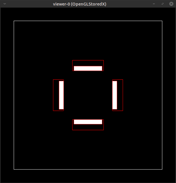
ここまでの実行が終わった状態を下の図に示します。
The following figure shows the state that you have completed so far.
見難いので以下のコマンドで視点を変えます。
Change the viewpoint to make it easier to see with the following command.
/vis/viewer/set/viewpointThetaPhi 0 0 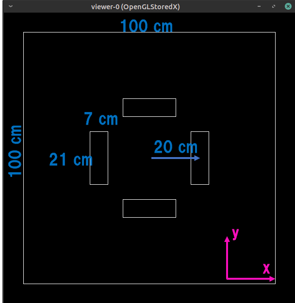
次は検出器ヘッドを鉛で埋めます(その上からNaIなどを配置します)
Next, fill the detector head with lead (later place NaI, etc. on it)
# Shielding
# Create the shielding volume
##
/gate/SPECThead/daughters/name shielding
/gate/SPECThead/daughters/insert box
/gate/shielding/geometry/setXLength  7. cm
/gate/shielding/geometry/setYLength 21. cm
/gate/shielding/geometry/setZLength 30. cm
/gate/shielding/placement/setTranslation  0. 0. 0. cm
/gate/shielding/setMaterial Lead
/gate/shielding/vis/setColor red
/gate/shielding/vis/forceWireframe
名前はshieldingとしていますが、任意です。大きさは全て先ほどのSPECTheadと同じです。mother volumeをSPECTheadとしていますので、配置する際は相対的な位置を指定します(SPECTheadの中心なので0,0,0)。
The name is shielding, but you can change it freely. The size is all the same as the SPECThead. Since the mother volume is the SPECThead, specify the relative position when arranging it (it is the center of the SPECThead, 0,0,0).
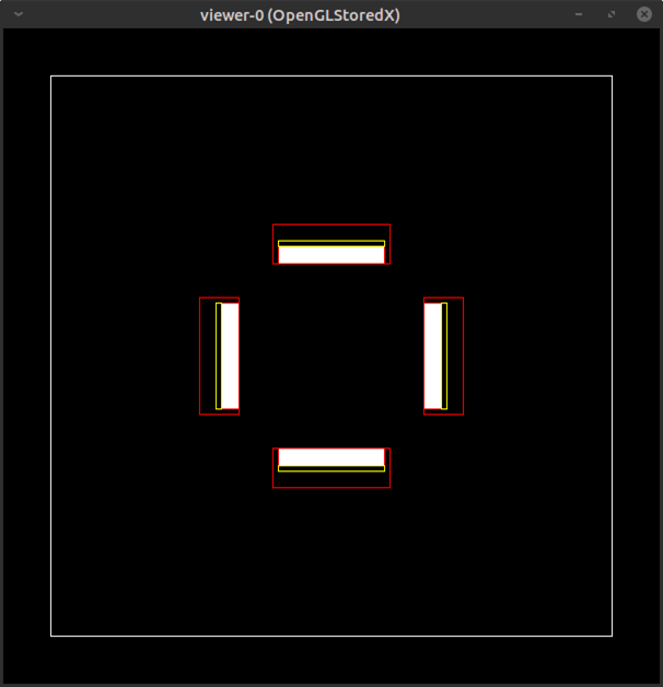
ここまでの状況を下の図に示します。
The following figure shows the state that you have completed so far.
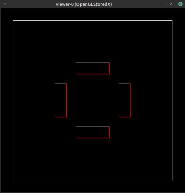
配置したのは1つだけですが、コピーして4つ配置されているSPECTheadをmother volumeとしているため、自動的に4つ作成されることになります。
Only one was placed, but since the SPECT head that was copied and placed four is the mother volume, four are automatically created.
次にコリメータを配置します
Then we’re going to put the collimators.
# Collimator
# Create a full volume defining the shape of the collimator
##
/gate/SPECThead/daughters/name collimator
/gate/SPECThead/daughters/insert box
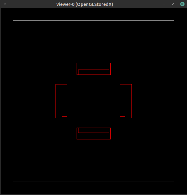
/gate/collimator/geometry/setXLength 3. cm
/gate/collimator/geometry/setYLength 19. cm
/gate/collimator/geometry/setZLength 28. cm
/gate/collimator/placement/setTranslation -2. 0. 0. cm
/gate/collimator/setMaterial Lead
/gate/collimator/vis/setColor red
/gate/collimator/vis/forceWireframeこれもmother volumeがSPECTheadであり、相対的な位置(-2, 0, 0)に配置するという点に注意してください。コリメータを配置した結果は下図の通りです。
Please note that mother volume is SPECThead, and collimator is located at the relative position (-2, 0, 0). The result of placing the collimator is shown below.
これも1つ配置するコマンドしか打っていませんが、mother volumeのSPECTheadがコピーされているため、コリメータも4つできることになります。
This time too, I wrote the command to place only one collimator. However, since the SPECT head of the mother volume has been copied, four collimators can be created.
次に鉛の板に空気の穴を開けることで、コリメータにしていきます。孔の形は六角形とします。円柱はZ軸に沿った方向しか作成できないため、作成したあとにY軸に対して90度回転させます。またmother volumeはcollimatorであるため、配置位置は指定なし(中心)としています。
Next, we will make a collimator by punching air holes in the lead plate. The shape of the hole is hexagonal. Since the cylinder can be created only along the Z axis, rotate it 90 degrees with respect to the Y axis after creating it. Since the mother volume is a collimator, the placement position is not specified (center).
#
# Insert the first hole of air in the collimator
##
/gate/collimator/daughters/name hole
/gate/collimator/daughters/insert hexagone
/gate/hole/geometry/setHeight 3. cm
/gate/hole/geometry/setRadius .15 cm
/gate/hole/placement/setRotationAxis 0 1 0
/gate/hole/placement/setRotationAngle 90 deg
/gate/hole/setMaterial Air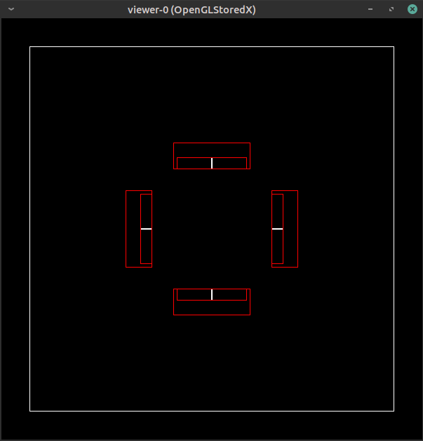
また視点を変えます。拡大もします。
Change view point again and zoom it.
/vis/viewer/set/viewpointThetaPhi  90 0
/vis/viewer/zoom 25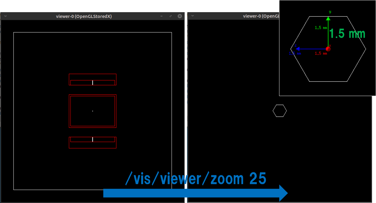
1つだけ開いているコリメータの穴を複製します。
Duplicate one open collimator hole.
#
# Repeat the hole in an array
##
/gate/hole/repeaters/insert cubicArray
/gate/hole/cubicArray/setRepeatNumberX 1
/gate/hole/cubicArray/setRepeatNumberY 52
/gate/hole/cubicArray/setRepeatNumberZ 44
/gate/hole/cubicArray/setRepeatVector 0. 0.36 0.624 cmy軸方向に0.36cm間隔で52個に、z軸方向に0.624cm間隔で44個に複製します。最初の1個の座標を中心とします。
52 pieces are copied at 0.36 cm intervals in the y-axis direction and 44 pieces are made at 0.624 cm intervals in the z-axis direction. Center the first one coordinate.
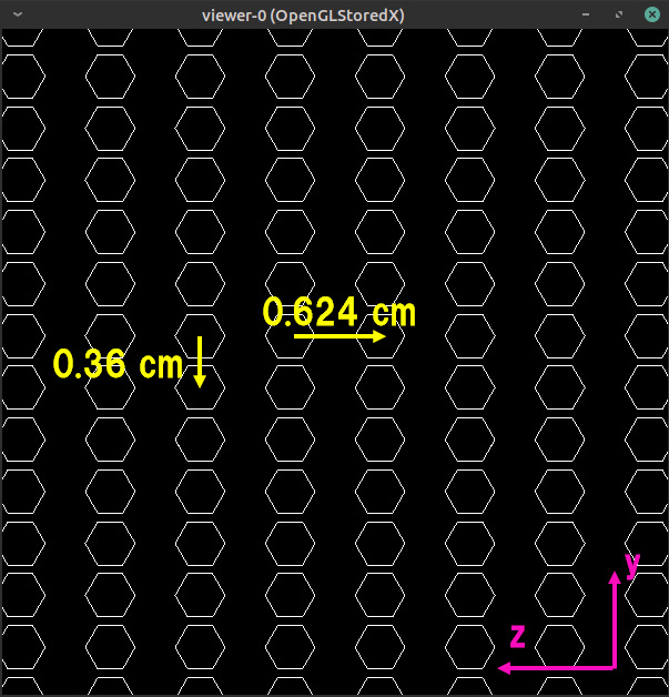
さらにyz方向に直線的にずらして配置します。これでコリメータの完成です。
Furthermore, it is arranged by linearly shifting in the yz direction. This completes the collimator.
# Repeat these holes in a linear
##
/gate/hole/repeaters/insert linear
/gate/hole/linear/setRepeatNumber 2
/gate/hole/linear/setRepeatVector 0. 0.18 0.312 cm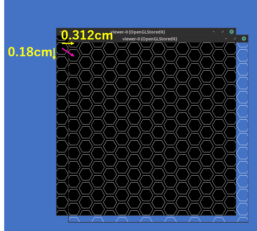
ここまでの結果は下図の通りです。
The results so far are shown below.
次にNaIクリスタルを配置します
Next, place the NaI crystal.
# CRYSTAL
# Create the crystal volume
##
/gate/SPECThead/daughters/name crystal
/gate/SPECThead/daughters/insert box
/gate/crystal/geometry/setXLength 1. cm
/gate/crystal/geometry/setYLength  19. cm
/gate/crystal/geometry/setZLength  28. cm
/gate/crystal/placement/setTranslation  0. 0. 0. cm
/gate/crystal/setMaterial NaI
/gate/crystal/vis/setColor yellow
mother volumeがSPECTheadであることに注意して配置位置を指定します。
Specify the placement location by noting that mother volume is SPECThead.
NaIクリスタルの後ろにback component (光電子増倍管など?)を配置します。成分はガラスです。
Place the back component (for example, photomultiplier?) behind the NaI crystal.The material is glass.
# BACK-COMPARTMENT
# Create the back-compartment volume
##
/gate/SPECThead/daughters/name compartment
/gate/SPECThead/daughters/insert box
/gate/compartment/geometry/setXLength 2.5 cm
/gate/compartment/geometry/setYLength 19. cm
/gate/compartment/geometry/setZLength 28. cm
/gate/compartment/placement/setTranslation   1.75 0. 0. cm
/gate/compartment/setMaterial Glass
/gate/compartment/vis/setColor grey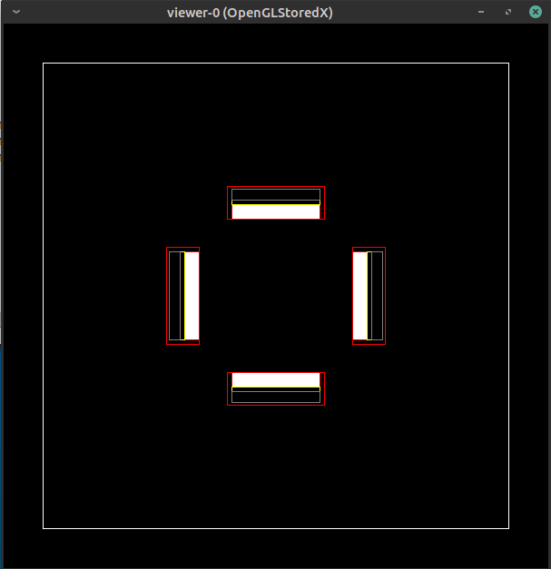
寝台を配置します。mother volumeはworldです。
Place patient table. Mother volume is world.
# TABLE
# Create the table volume
##
/gate/world/daughters/name table
/gate/world/daughters/insert box
/gate/table/geometry/setXLength 0.6 cm
/gate/table/geometry/setYLength 8. cm
/gate/table/geometry/setZLength 34. cm
/gate/table/placement/setRotationAxis 0 0 1
/gate/table/placement/setRotationAngle 90 deg
/gate/table/placement/setTranslation 0. -5.3 0. cm
/gate/table/moves/insert translation
/gate/table/translation/setSpeed 0 0 0.04 cm/s
/gate/table/setMaterial Glass
/gate/table/vis/setColor grey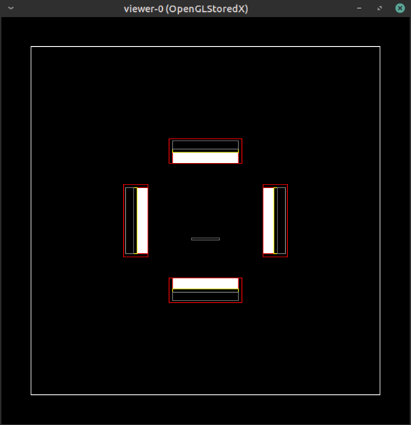
ファントムを配置します。mother volumeはworldです。
Place phantom. Mother volume is world.
# PHANTOM
# Create the phantom volume
##
/gate/world/daughters/name Phantom
/gate/world/daughters/insert cylinder
/gate/Phantom/geometry/setRmax 5.  cm
/gate/Phantom/geometry/setRmin 0. cm
/gate/Phantom/geometry/setHeight 20. cm
/gate/Phantom/placement/setTranslation 0. 0. -6. cm
/gate/Phantom/moves/insert translation
/gate/Phantom/translation/setSpeed 0 0 0.04 cm/s
/gate/Phantom/setMaterial Water
/gate/Phantom/vis/setColor blue
/gate/Phantom/vis/forceWireframe
見やすくするために以下のコマンドを打ちます。
For easier viewing, execute the following command:
/vis/viewer/set/auxiliaryEdge
/vis/viewer/set/viewpointThetaPhi  65 55
/vis/viewer/zoom 2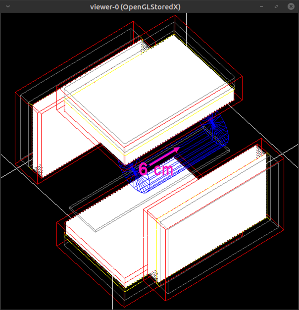
線源を配置する円柱(半径2cm, 長さ5cm)をz=-6cmの座標に配置します
mother volumeはPhantomです。
geometryの名前はmovsourceとします。あとでガンマ線の放出範囲を制限(confine)する際にこの名前を使用します。
Create a cylinder (radius 2 cm, length 5 cm) where the source of the ray will be placed. Slide it 6 cm in the z axis direction.
The mother volume is Phantom. The geometry is named movsource. Use this name when you later limit the range of gamma rays emitted.
# SOURCE
# Add an extra object for source confinement
##
/gate/Phantom/daughters/name movsource
/gate/Phantom/daughters/insert cylinder
/gate/movsource/geometry/setRmax 2.  cm
/gate/movsource/geometry/setRmin 0. cm
/gate/movsource/geometry/setHeight 5. cm
/gate/movsource/placement/setTranslation 0. 0. -6. cm
/gate/movsource/setMaterial Water
/gate/movsource/vis/setColor magenta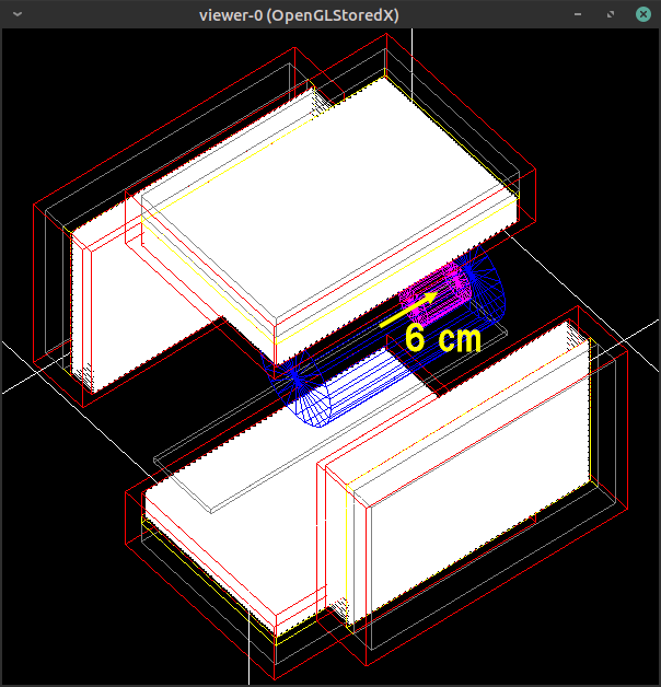
システムにattachします。システムはこちらにかかれているようにcrystalとpixelがありますが、本サンプルコードではcrystalのみattachしています。
Attach to the system. The system has crystal and pixel as described here, but only crystal is attached in this sample code.
/gate/systems/SPECThead/crystal/attach crystal

/gate/systems/SPECThead/describe     #詳細表示
Sensitive detector
Sensitive detector(SD)に登録して情報を収集できる状態にします。
SDにはcrystalSDとphantomSDがあり、それぞれ収集できるデータが異なります。
Register the placed geometry in the Sensitive detector (SD) so that information can be collected.
SD has crystalSD and phantomSD, and different data can be collected.
/gate/crystal/attachCrystalSD

/gate/Phantom/attachPhantomSD
/gate/movsource/attachPhantomSD
/gate/table/attachPhantomSD
/gate/compartment/attachPhantomSD
/gate/shielding/attachPhantomSD
/gate/SPECThead/attachPhantomSD
/gate/collimator/attachPhantomSD
Physics list
physics listを指定します。
Specify the physics list.
#  P H Y S I C S
#####
/gate/physics/addProcess PhotoElectric
/gate/physics/processes/PhotoElectric/setModel StandardModel

/gate/physics/addProcess Compton
/gate/physics/processes/Compton/setModel PenelopeModel

/gate/physics/addProcess RayleighScattering
/gate/physics/processes/RayleighScattering/setModel PenelopeModel

/gate/physics/addProcess ElectronIonisation
/gate/physics/processes/ElectronIonisation/setModel StandardModel e-

/gate/physics/addProcess Bremsstrahlung
/gate/physics/processes/Bremsstrahlung/setModel StandardModel e-

/gate/physics/addProcess eMultipleScattering e-

/gate/physics/processList Enabled
/gate/physics/processList Initialized
Cut
cutを指定します。二次粒子の飛程がcut以下の場合には生成されません。
Setting of the “cut”. It will not be generated if the range where the secondary particles fly is below “cut”.
#  C U T S
#####
# Cuts for particle in WORLD
##
/gate/physics/Gamma/SetCutInRegion   SPECThead 0.1 cm
/gate/physics/Electron/SetCutInRegion   SPECThead 1.0 cm
Initilization
準備ができたので初期化します
Ready to go. Let’s initialize.
# I N I T I A L I Z A T I O N
#####
/gate/run/initialize
SPECT.macの中身は以上になります。次にsecondPart.macを読み込みます。
This is the content of the SPECT.mac. Next, load the secondPart.mac.
/control/execute secondPart.macsecondPart.mac
secondPart.macの始めに以下のようなコマンドが書かれています。
The following commands are written at the beginning of the secondPart.mac:
# Show how the geometry moves with time
# ! After the initialization !
##
/control/execute MoveVisu.mac本サンプルコードは時間とともにジオメトリや線源を動かしているため、どのように動くかを視覚的に確認する必要があります。ある時点でどのような配置になっているかを視覚化するコマンドはMoveVisu.macに記述されていますので、読み込みます。
This sample code is moving geometry and sources over time, so you need to see how it works. The commands that visualize what the deployment looks like at some point in time are documented in MoveVisu.mac and should be read.
Source
次に線源に関する記述です。線源に関する記述は/gate/run/initializeのあとに書かなければなりません。
The following is a description of the source of radiation: The source description must after /gate/run/initialize.
# D E F I N E  T H E  S O U R C E
#####
/gate/source/addSource SourceConfinement
/gate/source/SourceConfinement/gps/type Volume
/gate/source/SourceConfinement/gps/shape Cylinder
/gate/source/SourceConfinement/gps/radius 2. cm
/gate/source/SourceConfinement/gps/halfz 14.5 cm
/gate/source/SourceConfinement/gps/centre 0. 0. 0. cm
/gate/source/SourceConfinement/gps/particle gamma
/gate/source/SourceConfinement/gps/energy 140. keV
/gate/source/SourceConfinement/setActivity 30000. Bq
/gate/source/SourceConfinement/gps/angtype iso
これは半径2cmで長さ14.5cmの長い円柱形(volume)です。書かれている通り140keVのガンマ線を30000Bqの強度で放出します。放出角度は4π方向です。
This is a long cylindrical shape with a radius of 2 cm and a length of 14.5 cm. As written, it emits 140 keV gamma rays with an intensity of 30,000 Bq. The emission angle is 4π.
動く線源のジオメトリから放出させるため、ガンマ線の発生範囲を線源geometryに制限(confine)します。これは以下のコマンドで可能です。
In order to emit gamma rays from the moving source geometry, the gamma ray generation range is limited to the source geometry. This is possible with the following command (confine).
# Define a confinement
# the activity cannot move with time so the attenuating medium is moved and the activity is forced to be in the
# attenuating medium
/gate/source/SourceConfinement/gps/confine movsourceDigitizer
次にsensitive detectorに登録したvolumeから取得したHit情報をSingleの情報に変換する過程の電気的処理(digitizer)を記載します。
Next, we will explain the process (digitizer) that converts hit information obtained from a volume registered as a sensitivity detector into single information.
# D I G I T I Z E R
#####
/gate/digitizer/Singles/insert adder
/gate/digitizer/Singles/insert blurring
/gate/digitizer/Singles/blurring/setResolution 0.10
/gate/digitizer/Singles/blurring/setEnergyOfReference 140. keV
/gate/digitizer/Singles/insert spblurring
/gate/digitizer/Singles/spblurring/setSpresolution 2.0 mm
/gate/digitizer/Singles/spblurring/verbose 0
/gate/digitizer/Singles/insert thresholder
/gate/digitizer/Singles/thresholder/setThreshold 20. keV
/gate/digitizer/Singles/insert upholder
/gate/digitizer/Singles/upholder/setUphold 190. keV
これでエネルギーが10%@140keVで広がりを持つ(ボケる)ことになります。装置のエネルギー分解能を模擬できます。
また、検出座標も同じようにFWHM:2.0mmでボケさせて、空間分解能を模擬します。
検出するエネルギーの下限/上限は20keV/190keVとしています。
This will spread the energy at 10%@140keV (blur). You can simulate the energy resolution of your device.
Similarly, the detected coordinates are also blurred by FWHM: 2.0 mm to simulate spatial coordinates.
The lower/upper limit of detected energy is 20keV/190keV.
Output
結果はROOT形式で取り出します。(ascii形式も使えますが、デフォルトでコメントアウトしています)
Results are retrieved in ROOT format (you can also use ascii format, but comments out by default).
# O U T P U T
#####
/gate/output/root/enable
/gate/output/root/setFileName benchSPECT
/gate/output/root/setRootSinglesAdderFlag 1
/gate/output/root/setRootSinglesBlurringFlag 1
/gate/output/root/setRootSinglesSpblurringFlag 1
/gate/output/root/setRootSinglesThresholderFlag 1
/gate/output/root/setRootSinglesUpholderFlag 1
上記の書き方では複数Hitがaddされた情報、エネルギーのボケ(blurring)、検出座標のボケ(Spatial blurring)、Threshold/Upholdの後の情報すべてを出力することになります。容量が大きくなるので必要なものだけ1としてください。
In the above writing method, information that multiple hits are added, energy blur (blurring), detection coordinate blur (Spatial blurring), and information after Threshold/Uphold are all output. Please note that output of all information will increase the capacity.
Random
乱数についてです
Setting of the random
#   R A N D O M
# JamesRandom Ranlux64 MersenneTwister
/gate/random/setEngineName Ranlux64
/gate/random/setEngineSeed 123456789
/gate/random/verbose 1
乱数発生アルゴリズムはRanlux64、種(Seed)は123456789、ログ出力はlevel 1としています。
アルゴリズムはJamesRandom、Ranlux64、MersenneTwisterの中から選びます。
The random number generation algorithm uses Ranlux64, with a seed of 123456789.The output of the log is simplified (level 1).
The algorithms are chosen from James Random, Runlux64, and Mersenne Twister.
[blogcard url=”http://www.math.sci.hiroshima-u.ac.jp/~m-mat/TEACH/ichimura-sho-koen.pdf”]
↑メルセンヌ・ツイスター法は日本人が考案したもので、現在でも使われます。
The Mercene Twister method was invented by the Japanese and is still in use today.
Projection
SPECTheadとOpticalsystemだけが、PROJECTION形式で出力が可能です。
Only SPECThead and Opticalsystem can output the data in Projection format.
# P R O J E C T I O N
#####
/gate/output/projection/enable
/gate/output/projection/setFileName YourProjection
/gate/output/projection/pixelSizeX 0.904 mm
/gate/output/projection/pixelSizeY 0.904 mm
/gate/output/projection/pixelNumberX 128
/gate/output/projection/pixelNumberY 128

# Specify the projection plane (XY, YZ or ZX)
##
/gate/output/projection/projectionPlane YZ上記の記述ではYZ平面の情報を128×128マトリクスで出力します。各マトリクスの大きさは0.904×0.904mmです。このデータはProminence processorなどで再構成可能です。
The above description provides information on the YZ plane in a 128×128 matrix.Each matrix is 0.904 x 0.904 mm in size, and this data can be reconstructed by the Prominence processor.
Acquisition time
撮像時間を指定します。
Specify the acquisition time.
# E X P E R I M E N T
#####
/gate/application/setTimeSlice      1. s
/gate/application/setTimeStart      0. s
/gate/application/setTimeStop       2. s
合計2秒間の撮像ですが、1秒毎に区切ります。この際にジオメトリや線源が動きます。
The total acquisition time is set to 2 seconds, but the data is split in 1 second. At this time, geometry and radiation source move.
Verbose
ログの出力の細かさを指定します。
Specify the detail of log output.
# V E R B O S I T Y
#####
/control/execute Verbose.mac
Run
以下のコマンドで計算が始まります。
The following command runs the simulation.
# L E T' S   R U N   T H E   S I M U L A T I O N  !
#####
/gate/application/startDAQ
DAQはData AcQuisitionの略だったはず
DAQ means Data AcQuisition, maybe.