GATEの使い方 10 ~Voxelized phantom & source~

How to use GATE 10
今回は画像からファントムを作成する方法と線源の配置を決める方法についてです。
Today’s topic is how to create phantoms from images and determine the distribution of sources from images.
複雑な形状のファントムは、画像情報を用いことで簡単に作成可能です。小さなボクセルによって複雑な形を表現したファントムをVoxelized phantomといいます。
Phantoms with complicated shapes can be easily created using image information. The phantom which is made from small voxel is called the Voxelized phantom.
また、線源も画像の画素値をもとに配置することができ、それをVoxelized sourceと呼びます。
The distribution of the radiation source can also be based on the pixel value of the image and it is called Voxelized source.
GATEではこのような機能が提供されています。
GATE provide these function.
これを読めばVoxelized phantomとVoxelized sourceの使い方が理解できます!
You can understand how to use the voxelized phantom and voxelized source in the GATE simulation if you read this article.
GATEの使い方 10
How to use the GATE
Voxelized phantom
複雑な形状のファントムを作成する場合、円柱、球や直方体などを組み合わせて作ることは面倒です。
it is troublesome to create a complicated phantom using a combination of cylinders, spheres, and rectangular.
医療の分野では人体を模擬したい場合が多く、CT画像をシミュレーションに組み込んで計算することが多いです。もちろん、他のシミュレーションソフトと同様にGATEでもそれが可能です。
In the field of medicine, we often want to simulate the human body. Therefore, it is often calculated by incorporating CT images into simulation. Of course, like any other simulation software, GATE can do that.
使用可能な画像の形式はASCII、Interfile、Analyze、MetaImage、DICOM形式です。
The available image formats are ASCII, Interfile, Analyze, MetaImage, and DICOM.
今回はDICOM画像ではなくAnalyze形式を使用します。ただし、ImageJ(Fiji)を使えばDICOMからAnalyze形式への変換は簡単です。
This time, we will use the Analyze format instead of the DICOM image. ImageJ (Fiji) makes conversion from DICOM to Analyze easy.
この画像からファントムを作成する機能はGATE ver.7.0から使用可能になりましたので、古いversionではできません。
This function (create phantom from image) is available from GATE ver.7.0, so it cannot be done in old version.
VoxelizedPhantomの作成方法は3つあります。
There are three ways to create a Voxelized Phantom:
1. RegularParameterization
2. NestedParameterization
3. RegionalizedParameterization
RegularParameterization
この方法は一番初めに提案されてもので、物質の種類が少ないほど計算が速いという特徴があります。物質は3つ程度(空気、水、骨)にするとよいようです。
This method is first proposed, and it has the characteristic that the calculation is faster when there are fewer types of substances. Substances should be limited to 3 (air, water, bone).
以下のコマンドによって物質が同じときに境界が無視され、計算速度が向上します。
The following commands speed up the calculation. The boundary between the voxels of the same material is ignored.
# The "hof_brain" is name of voxelized phantom
/gate/hof_brain/setSkipEqualMaterials             1
この方法は徐々に使われなくなっているようです。
This method is gradually becoming obsolete.
NestedParameterization
この方法の利点はメモリを有効に使えることです。ただし、サイズは固定でギャップは作ることができません。たとえ同じ物質であろうと、ボクセルの境界では必ず止められる(stepが区切られる)ため計算時間がかかるという欠点があります。
The advantage of this method is that you can use memory effectively.However, the size is fixed and you cannot make a gap.The drawback is that even if it is the same material, it is always stopped at the voxel boundary (a step is separated) and therefore takes time to calculate.
RegionalizedParameterization
この方法はもっとも新しい方法で、メモリの消費が少なく計算時間を短縮することができます。ただし、構造が複雑な場合や、物質の種類が多い場合にはこの効果が得られません。
This method is the most recent and can consume less memory and reduce computation time.However, complex structures and many types of substances do not have this effect.
Voxelized phantomを作成するにあたって用意するものは以下の2つです。
・物質情報を書いたテキストファイル(例えばattenuation.dat)
・画像(*.hdr, *.img)
The following two items are required to create a Voxelized phantom.
・A text file that describes substance information (for example, attenuation.dat)
・Image (*.hdr, *.img)
物質情報を書いたテキストファイルの書式は以下のようになります。
The figure below shows the format of a text file containing substance information.
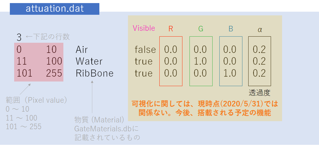
最初に何個の範囲に分割するかを記載します。上の例では3です。
First, describe how many ranges you want to divide. In the above example, it is 3.
次に画素値、物質、可視化に関する記述を行います。可視化に関しては現在(2020/5/31)の段階ではサポートされていませんので、意味はありません。
Next, we will describe pixel values, materials, and visualization. Visualization is not supported at this time (2020/5/31), so it is meaningless.
範囲は画素値(0~255)で指定します。8 bitなので256諧調ですね。16 bitは試していないので分かりません。(32bit float画像は使えないようです。小数が使えない。)
The substance to be applied to the phantom is specified by the pixel value (0 to 255) of the image. I haven’t tried 16 bit images, so I don’t know. (32bit float images cannot be used.)
物質に関してはGateMaterials.dbに書いてある物質を記載します。新しい物質を使用したい場合にはGateMaterials.dbに追加すればOKです。
In “attanuation.dat”, describe the substances written in GateMaterials.db. If you want to use a new material, just add it to GateMaterials.db.
次に画像です。今回使用する画像はここからダウンロードしました。Fijiを使って、少し手を加えています。
Next, prepare the image. The image used this time is downloaded from here. I’m using Fiji to make some changes.
Fijiは以下のコマンドで起動します。(vGATE ver8.2を使用した環境です)
vGATE ver8.2ではデフォルトでインストールされていますが、Fijiをインストールしていない場合はインストールしておいてください。
Fiji can be started with the following command. (This is an environment using vGATE v8.2)
If you have not installed Fiji (not using vGATE), please install it.
imagej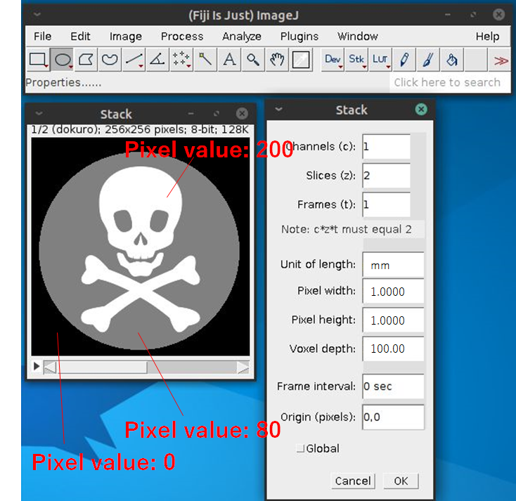
256×256×2スライス (256mm×256mm×200mm)の8 bit画像です。
情報は「Image→Properties…」から変更可能です。
It is an 8-bit image of 256 × 256 × 2 slices (256 mm × 256 mm × 200 mm).
Information can be changed from “Image → Properties…”.
画像をAnalyze形式で保存する方法は以下の通りです。
To save the image in Analyze format, follow these steps:
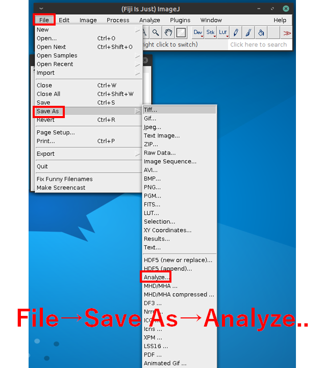
今回はdokuro.hdrとdokuro.imgとして保存します。
This time, save the images as dokuro.hdr and dokuro.img.
では、実際にマクロファイルの中でどのような記載が必要なのかを説明します。
I will explain what is required in the macro file to use voxelized phantom.
/gate/world/daughters/name vox_phan
#/gate/world/daughters/insert ImageRegularParametrisedVolume
/gate/world/daughters/insert ImageNestedParametrisedVolume
#/gate/world/daughters/insert ImageRegionalizedVolume
/gate/vox_phan/geometry/setImage dokuro.hdr
/gate/vox_phan/geometry/setRangeToMaterialFile attenuation.dat
/gate/vox_phan/placement/setTranslation 0. 0. 0. mm
/gate/vox_phan/placement/setRotationAxis 1 0 0
/gate/vox_phan/placement/setRotationAngle 0 deg
/gate/vox_phan/attachPhantomSD
前述したようにVoxelized phantomの作成方法は3つありますので、1つだけ選んでください。上の例ではImageNestedParametrisedVolumeを有効にしています。
As mentioned earlier, there are three ways to create a Voxelized phantom, so please select only one. In the above example, ImageNestedParametrisedVolume is enabled.
Voxelized phantomを回転させたい場合には回転させる軸と角度を指定します。上の例では回転させる必要が無かったので0 degとしています。
Specify the axis and angle to rotate the Voxelized phantom if you want to rotate it. In the above example, there is no need to rotate it, so it is set to 0 deg.
以下のマクロファイルを使って実行した結果です。
The figure below is the result of executing using the following macro file.
Gate

PreInit > /control/execute myPET_DMI_vox_phn.mac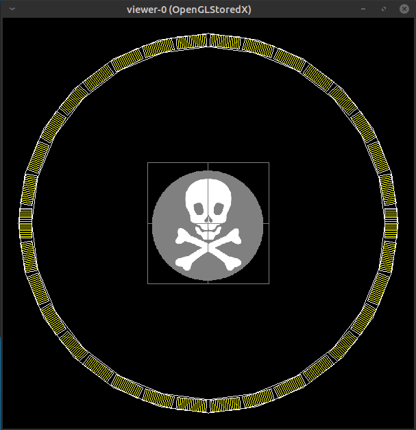
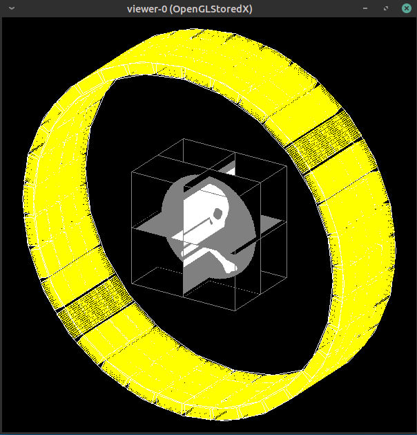
これでVoxelized phantomの完成です。
The Voxelized phantom is complete.
Voxelized source
次は画像の画素値をもとに線源の分布を指定するVoxelized sourceです。
Next is a voxelized source that specifies the distribution of the radiation source based on the pixel values of the image.
この機能はGATE ver7.1以降で使用可能です。
This function can be used with GATE ver7.1 or later.
読み取れる画像の形式はASCII、Interfile、Analyze、MetaImage、DICOMです。今回もAnalyze形式を使用します。
The image formats that can be read are ASCII, Interfile, Analyze, MetaImage, and DICOM. We will use the Analyze format again.
用意するものは以下の2つです。
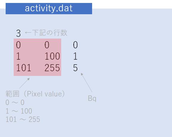
・線源強度を書いたテキストファイル(例えばactivity.dat)
・画像(*.hdr, *.img)
There are two items to prepare.
・A text file that describes the source intensity (e.g. activity.dat)
・Image (*.hdr, *.img)
画像に関してはVoxelized phantomと一緒です(同じファイルをそのまま使ってもOK)。Analyze形式で保存します。
As for the image, it is the same as Voxelized phantom (You can even use the same file as is). Save in Analyze format.
以下のコマンドでVoxelized sourceを使用します。
画像はdokuro.hdrの解像度を32x32x2に落としてdokuro32.hdrという名前にしました。
You can use Voxelized source with the following command.
The image was saved as dokuro32.hdr with the resolution of dokuro.hdr reduced to 32x32x2.
/gate/source/addSource vox_src voxel
/gate/source/vox_src/reader/insert image
/gate/source/vox_src/imageReader/translator/insert range
/gate/source/vox_src/imageReader/rangeTranslator/readTable activity.dat
/gate/source/vox_src/imageReader/rangeTranslator/describe 1
/gate/source/vox_src/imageReader/readFile dokuro32.hdr
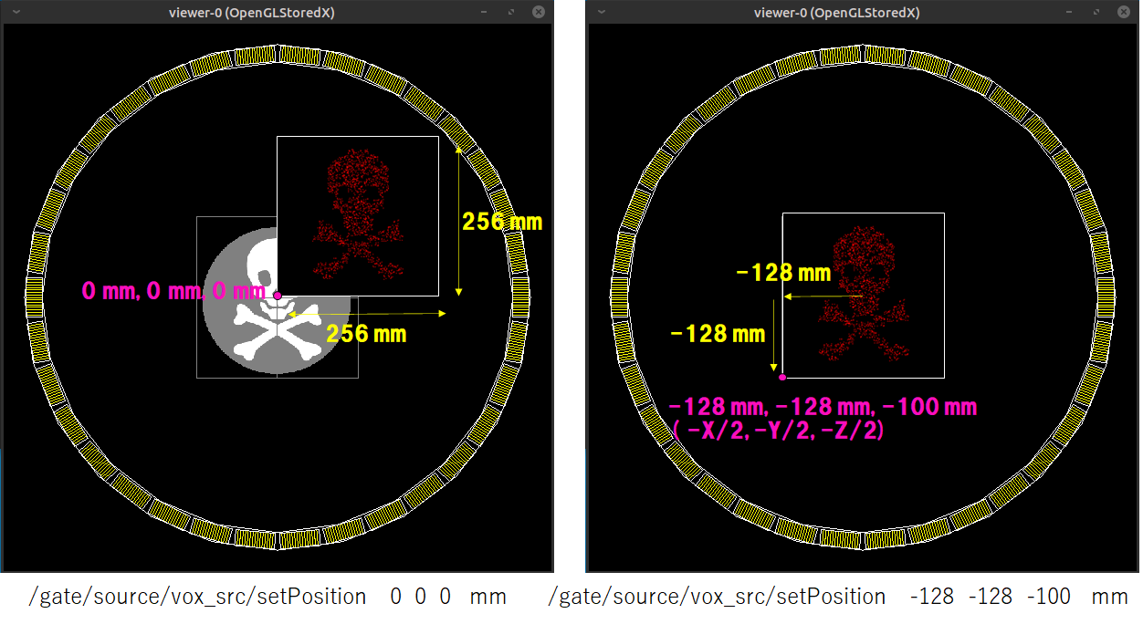
/gate/source/vox_src/setPosition -128 -128 -100 mm
/gate/source/vox_src/gps/particle e-
/gate/source/vox_src/gps/energytype Mono
/gate/source/vox_src/gps/monoenergy 140. eV
/gate/source/vox_src/gps/angtype iso
/gate/source/vox_src/gps/mintheta 0. deg
/gate/source/vox_src/gps/maxtheta 90. deg
/gate/source/vox_src/gps/minphi 0. deg
/gate/source/vox_src/gps/maxphi 360. deg
/gate/source/vox_src/gps/confine NULL ここで注意しなければならないことはsetPositionの値です。原点を指定した場合には以下のような分布になります。そのため、画像サイズの半分だけXYZ方向にシフトした座標を指定する必要があります。
The thing to note here is the value of setPosition. If the origin is specified in setPosition, the distribution will be as follows. Therefore, it is necessary to specify the coordinates shifted in the XYZ directions by half the image size.
線源強度を書いたテキストファイルの書式は以下のようになります。
The format of the text file that describes the intensity of the radiation source is as follows.
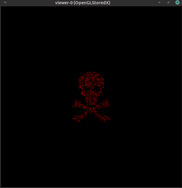
以下が実行結果です。低エネルギーの電子線を発生させています。
The following is the execution result. Generated a low-energy electron beam.
テキストファイル(activity.dat)と線源強度の関係がいまいちはっきり理解できなかったので、以下のように実験してみました。
I couldn’t quite understand the relationship between the text file (activity.dat) and the intensity of the radiation source, so I tried the following experiment.
他の条件は全て同じにして、線源分布のもとにする画像のマトリクスだけを変えました。片方は32×32マトリクスの2スライスの画像で、もう片方は256×256マトリクスの2スライスの画像です。サイズは等しく256×256 mmです。
All other conditions were the same, only the matrix of the image that was the source of the source distribution was changed. One is a 32 x 32 matrix, 2 slice image, and the other is a 256 x 256 matrix, 2 slice image. The size is equally 256 x 256 mm.
白色のピクセルの画素値は1で黒色のピクセルは画素値0です。
画素値から計算すると白色のピクセルの数はそれぞれ414個と27188個です。
The white pixel value is 1 and the black pixel is 0.
Calculating pixel values, the number of white pixels is 414 and 27188, respectively.
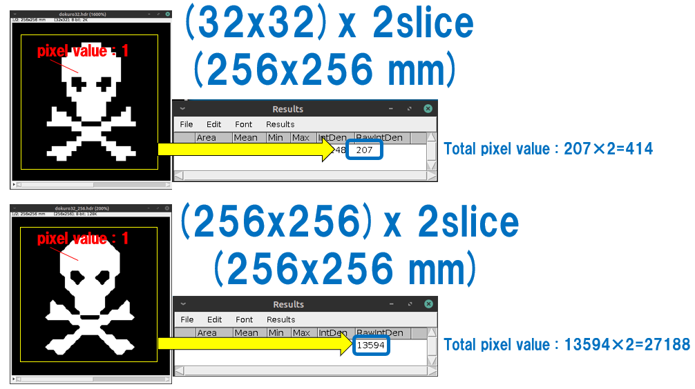
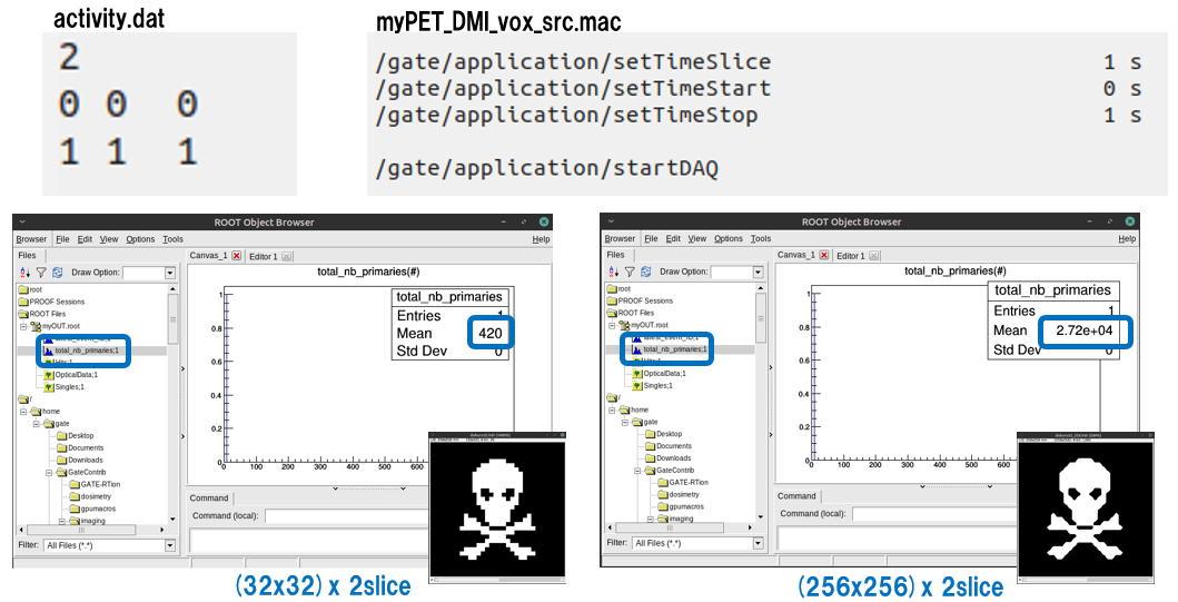
結果のROOTファイルを見てみると、発生した粒子の数が大きく違うのが分かります。また、画素値1のピクセルの総数とも合致しています。
よって各マトリクスから指定したBqの分だけ粒子が発生していることになります。
Looking at the resulting ROOT file, you can see that the number of particles generated is very different. It also matches the total number of pixels with a pixel value of 1.
Therefore, each matrix generates as many (Bq) particles as you specify.
これが使えればより実際的なシミュレーションができますね
If you can use this, you can do a more realistic simulation.